SPI (Serial Peripheral Interface)
The Serial Peripheral Interface (SPI) is a synchronous serial communication interface. The interface was developed by Motorola in the mid-1980s and has become a de facto standard (achieved a dominant position by public acceptance) . SPI devices communicate in full duplex mode using a master–slave architecture usually with a single master. The master (controller) device originates the frame for reading and writing of data and Multiple slave-devices can be supported through selection with individual chip select (CS), sometimes called slave select (SS) lines. The Application like Sensors: temperature, pressure, ADC, touchscreens and Memory: flash and EEPROM and others.
SPI is a synchronous, full duplex main-subnode based interface. The data from the main or the slave/sub-node is synchronised on the rising or falling clock edge. Both main and sub-node can transmit data at the same time. The SPI interface can be either 3-wire or 4-wire. lets focuses on the popular 4-wire SPI interface.
4-wire SPI devices have four signals:
1) Clock (SPI CLK, SCLK)
2) Chip select (CS)
3) main out, subnode in (MOSI)
4) main in, subnode out (MISO)
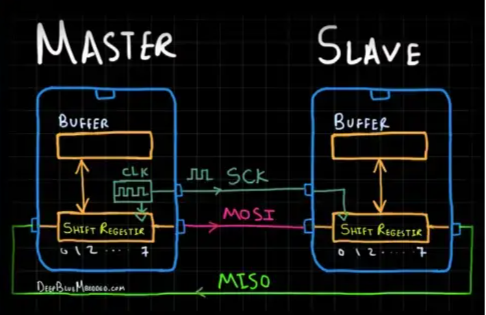
The device that generates the clock signal is called the main. Data transmitted between the main and the sub-node/slave is synchronised to the clock generated by the main. SPI devices support much higher clock frequencies compared to I2C interfaces. SPI interfaces can have only one main and can have one or multiple sub-nodes/slave.
The chip select signal from the main is used to select the sub-node/slave. This is normally an active low signal and is pulled high to disconnect the sub-node/slave from the SPI bus. When multiple sub-nodes are used, an individual chip select signal for each sub-node is required from the main. In this article, the chip select signal is always an active low signal.
MOSI and MISO are the data lines. MOSI transmits data from the main to the subnode and MISO transmits data from the subnode to the main.
Data Transmission:
To begin SPI communication, the main must send the clock signal and select the sub-node/slave by enabling the CS signal. Usually chip select is an active low signal. hence, the main must send a logic 0 on this signal to select the sub-node. SPI is a full-duplex interface. both main and sub-node can send data at the same time via the MOSI and MISO lines respectively. During SPI communication, the data is simultaneously transmitted (shifted out serially onto the MOSI/SDO bus) and received (the data on the bus (MISO/SDI) is sampled or read in). The serial clock edge synchronises the shifting and sampling of the data.
Recommended by LinkedIn
Clock Polarity and Clock Phase:
The SPI interface provides the user with flexibility to select the rising or falling edge of the clock to sample and/or shift the data. the main can select the clock polarity(CPOL) and clock phase(CPHA). The CPOL bit sets the polarity of the clock signal during the idle state. The idle state is defined as the period when CS is high and transitioning to low at the start of the transmission and when CS is low and transitioning to high at the end of the transmission. The CPHA bit selects the clock phase. Depending on the CPHA bit, the rising or falling clock edge is used to sample and/or shift the data. The main must select the clock polarity and clock phase, as per the requirement of the subnode. Depending on the CPOL and CPHA bit selection, four SPI modes are available. Table 1 shows the four SPI modes.
The following figures show an example of communication in four SPI modes. In these examples, the data is shown on the MOSI and MISO line. The start and end of transmission is indicated by the dotted green line, the sampling edge is indicated in orange, and the shifting edge is indicated in blue. Please note these figures are for illustration purpose only. For successful SPI communications, users must refer to the product data sheet and ensure that the timing specifications for the part are met.
Multi-Subnode Configuration/ Independent slave configuration:
Multiple subnodes can be used with a single SPI main. The subnodes can be connected in regular mode or daisy-chain mode.In regular mode, an individual chip select for each subnode is required from the main. Once the chip select signal is enabled (pulled low) by the main, the clock and data on the MOSI/MISO lines are available for the selected subnode. If multiple chip select signals are enabled, the data on the MISO line is corrupted, as there is no way for the main to identify which subnode is transmitting the data.
As can be seen from Figure, As the number of subnodes increases, the number of chip select lines from the main increases. This can quickly add to the number of inputs and outputs needed from the main and limit the number of subnodes that can be used. There are different techniques that can be used to increase the number of subnodes in regular mode.
Daisy-Chain Method:
In daisy-chain mode, the subnodes are configured such that the chip select signal for all subnodes is tied together and data propagates from one subnode to the next. In this configuration, all subnodes receive the same SPI clock at the same time. The data from the main is directly connected to the first subnode and that subnode provides data to the next subnode and so on. In this method, as data is propagated from one sub-node to the next, the number of clock cycles required to transmit data is proportional to the sub-node position in the daisy chain. Daisy-chain mode is not necessarily supported by all SPI devices. we have to refer to the product data sheet to confirm if daisy chain is available or not.